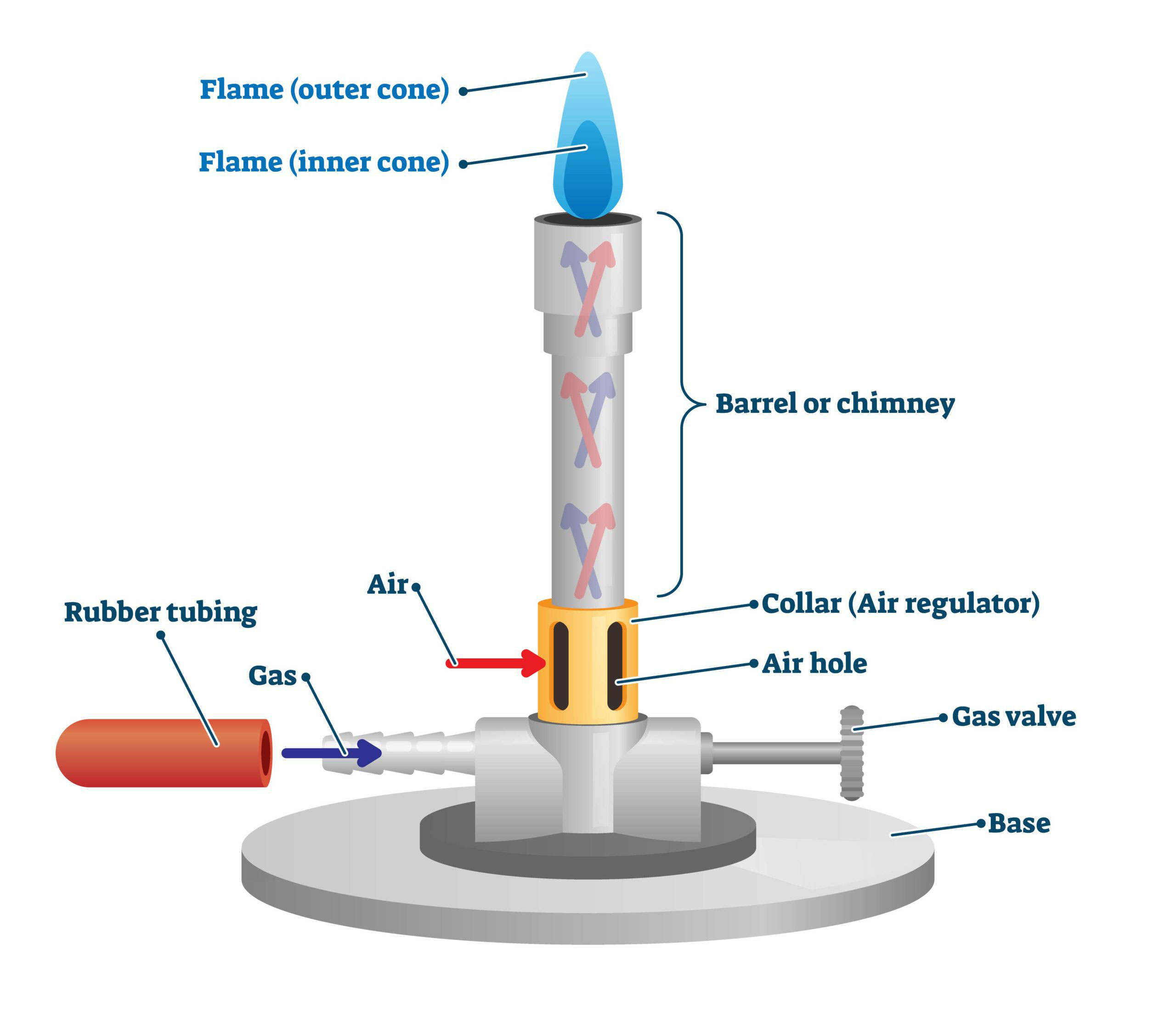
- Gas Inlet Valve: This valve controls the flow of gas to the burner.
- Gas Inlet Tube: The tube that connects the gas inlet valve to the burner.
- Air Intake Control: This control regulates the amount of air that is mixed with the gas, which affects the flame’s temperature.
- Mixing Tube: The tube where the gas and air mix before combustion.
- Burner Head: The part of the burner where the gas and air mixture ignites to produce a flame.
- Flame Stabilizer: This part of the burner helps to keep the flame stable by reducing turbulence.
- Base: The bottom part of the burner that supports it.
- Gas Supply Hose: The hose that connects the gas source to the gas inlet valve.
Bunsen Burners are commonly used in laboratories for heating, sterilization, and combustion reactions. The burner operates by mixing gas and air in the mixing tube and lighting it with a spark or lighter, producing a flame that can be adjusted by regulating the gas and air supply. The flame can be adjusted to produce different temperatures, depending on the application. The flame stabilizer helps to keep the flame steady and reduce turbulence, which can affect the temperature and stability of the flame.